MLX90640 Thermal Camera with Raspberry Pi 4
January, 2021
Overview
This page contains both the background and documentation for the PyPi package pithermalcam, which connects an MLX90640 thermal camera to a Raspberry Pi. The package is set up for quick and easy install or for cloning for more advanced users to play/tweak/develop further.
If you just want to get up and running as fast as possible, use the Parts Required/Hardware Setup sections to prepare the device, and then follow go to the Software Setup instructions to get up and running. If you just want to see what’s possible, jump down to the Usage and Results sections for pictures and videos of the results you can get.
Other sections go in depth for cloning or development. There’s a lot here, but I’ve been careful to split up different paths and to make this whole page modular. This enables you to jump to the parts you need and skip the ones that don’t apply to you.
Enjoy!
Contents
- Introduction
- Background
- Parts Required
- Hardware Setup
- Software Setup
- Development Copy Setup/Info
- Usage - The Three Approaches
- Results
- Conclusion
- Further Development
- Issue Reporting
Introduction
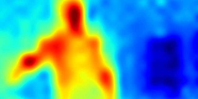
It’s winter, and my heating bill has gone up. I’ve also noticed a draft in certain areas of my house, so I decided it was time to fulfill my long-awaited dream of getting a thermal camera. These have generated some buzz of late as potential Covid temperature detectors, but I was more interested in seeing where there’s an insulation problem in my house that I might fix, or to detect leaks in pipes. Also, fun to play with!
Cameras such as these can produce images like this one, showing where heat is leaving a building:
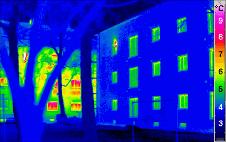 Passivhaus Institut, CC BY-SA 3.0, via Wikimedia Commons
Initially I researched buying or renting such a camera, but the buying options tend to start at $200 for the basic smartphone version, and go up to nearly $1,000. My local Lowe’s has such cameras for rent as well but they cost $50 for 24 hours!
I’ve long been a Raspberry Pi fan so when I saw that rental price I decided to see what options were available for the Pi. I quickly found the MLX90640 camera which costs only $60; at this price I’d get a cool gadget to play with, be able to evaluate my house for leaks, and use it as a security camera when I’m done. Perfect.
I would of course also need a raspberry pi and accompany equipment but I had some of that and would be able to reuse it all for other projects as well. This was also a great excuse to finally upgrade from the Pi 3B+ I had to a Pi 4.
Of note: The resolution on this camera is much lower so we’ll never get pictures like the above, but a mere few years ago even the best cheaper camera had only an 8x8 resolution, which is nearly unusable for projects like this. Jumping up to 24x32 resolution of the MLX90640 is a 12-fold increase for about the same price! It seems we’ve finally reached the point where cheap homemade thermal cameras are worth buying.
The below guide is meant to be a start-to-finish overview of the parts, setup, install, and use of this project for any who want to do likewise or build on it further. I don’t cover everything needed to work with a Raspberry Pi itself as there are plenty of other guides for that out there, but I try to touch on any and all pieces related to this project directly, at least to get it up and running.
Background
There were several similar projects already online, and I ended up taking pieces of two as my baseline, mixing and matching, and adding web streaming from a third. The results of that work are placed here for others to use directly or as a baseline for further develoment. The code is also available in the Github Repo corresponding to this page (link at top). The license is an AGPL-3.0 License, so if you make changes and publish, you’ll need to publish the code with it.
Thanks are owed to those three other projects: namely, Joshua Hrisko’s article at Maker Portal, High Resolution Thermal Camera with Raspberry Pi and MLX90640, Валерий Курышев’s article under the name Walker2000 at Habr, Making a DIY thermal camera based on a Raspberry Pi, and Adrian Rosebrock’s article OpenCV – Stream video to web browser/HTML page. Their work was a BIG step forward as a starting point.
Parts Required
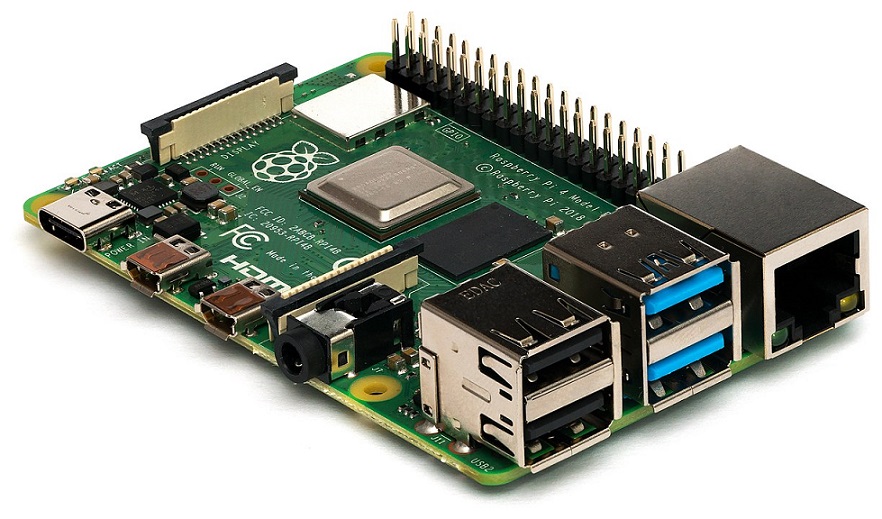 By Miiicihiaieil Hieinizilieir / Wikimedia Commons, CC BY-SA 4.0
Most of the parts lists I see are incomplete or link to pages with excessive costs (e.g. the Pi was invented specifically to be cheaper, so the basic version should never be > $35 before shipping). Below is a complete list of parts needed if you’re starting from scratch. The Pi-specific items can be reused for other projects; the camera is really the only item specific to this project.
Prices are approximate as of Jan. 2021:
- $60 + Shipping - MLX90640 Thermal Camera
- Note: The Thermal Camera comes in two flavors; one that’s 110 Degrees wide, one that’s 55. For purposes of this project the 55 would have been MUCH better but unfortunately it was sold out, so I had to make do with the with 110. This makes my thermal evaluation harder but the camera will likely be better for security camera use longer term. I haven’t had the chance to try it but I believe this code should work with the 55 Degree camear too.
- $1 + Shipping - STEMMA QT / Qwii with Female Sockets - This, or some other wiring solution, is needed to connect the camera to the Pi.
- $35 + Shipping - Raspberry Pi 4
- Note: This same project could likely be performed with other Raspberry Pi versions as well, e.g. a Pi 3 or the like. Some adjustments might be necessary though, and for purposes here the Pi 4 with 2 GB RAM is the one being used.
- $10-$30 - Raspberry Pi SD Card with Raspbian Installed - You can buy cards with Raspbian pre-loaded or get larger or faster cards from a variety of sources, so long as they follow the right guidelines.
- Note: If buying a card >=64GB make sure you check the instructions for exFAT formatting.
- ~$12 - Raspberry Pi Power Supply - You can get cheaper ones online, but they don’t always have sufficient power output (Amps). For a quality one check here
- Optional - Cooling Case with Fan - There are a variety of these to buy. You might well be fine without it, but the Pi 4 runs hot enough that I decided I wanted one simply to not need to worry about the CPU temp. Of note, if you have a Pi 4, looking for a case/fan in which the fan has 3 wires, not 2, so that you can connect it up to the Raspbian fan control which turns it on/off automatically as needed. The 2-wire versions will need adjustment or will be always on.
Other Things you might need:
- Portable battery with output ~ 3 Amps
- Screen for the Raspberry Pi
If you’re going to be walking around your house, or outside it, you’ll want some way to see the camera output live. As such, you’ll probably need a portable battery for the device and, if you’re not going to stream the video over your Wifi, you’ll want a screen to attach to the Pi.
I went with the Wifi option so I can’t speak to screens, but I’d imagine any of the many Pi-specific screens would be fine for this.
On the battery, the Pi 4 draws around 3 Amps so you’d want any backup battery which can feed a USB-C connection with ~3 Amps. I had a battery I use for my phone while traveling that worked great. You could try one with less power than this; just be aware that it might run a bit slower.
Hardware Setup
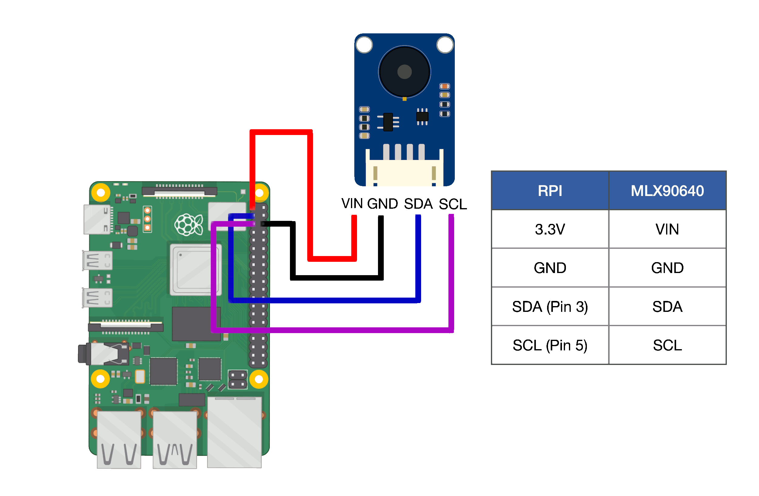 Image by Joshua Hrisko / Maker Portal, copied with permission and thanks
Most of the physical setup is straightforward. The one piece specific to this project is wiring the camera to the Pi itself, and luckly for us, Josh at Maker Portal has made the perfect diagram (above) for this and kindly agreed to let me put it here too.
The image shows where the camera connects to the Pi using the appropriate power and I2C pins. In my particular case I had a fan on the ground pin used here so I needed to move the ground wire to another ground on the Pi, but you can find another ground as needed in the GPIO pinout diagrams available in many places online.
Below is a picture of my device in final form. You can see the case I used (but would not recommend; better to get one a tad more open and with a variable speed fan) and the fact that I initially bought a Stemma connector with male ends meant I had to solder those to other wires to connect to the Pi. If you buy the right pieces the first time yours will look cleaner than this.
I found taping the camera to the case an easy way to make using the device simpler to work with.
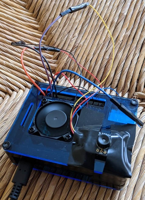 Final Device Assembled
Software Setup
This section discusses the software setup needed to get going.
Prerequisite/Setup
Prior to setting up the python library itself, you’ll need to perform some tweaks and installs to get ready:
1. apt-get Installs
Use apt-get to install the following packages: libatlas-base-dev python-smbus i2c-tools
2. Enable I2C and Increase Pi Baudrate
You’ll need to enable I2C on your Raspberry Pi and increase the baudrate. I2C can be enabled simply in the Pi Configuration via GUI or via typing sudo raspi-config and enabling it there.
To increase your baudrate, type sudo nano /boot/config.txt and find the line with dtparam=i2c_arm=on. Add i2c_arm_baudrate=400000 to the end of it, so the end result should look like:
 Section of /boot/config.txt after baudrate change.
Save the file and reboot the device when you’re done.
Note: In the first article I referenced, baudrates much higher than 400k were apparently tested; as high as 1M. I tested some higher rates but got many more errors at these levels. Running at higher rates also increases the risk of overheating as the maximum supported speed is apparently 400k. When I switched to the OpenCV approach (discussed below), 400k was fast enough to be usable. Since I want to reuse my Pi for other projects or as a security camera long term I stuck with the 400k. If you want the Matplotlib approach to work faster, as it did for the writer of that first article, this is likely what you’d need to change; just make sure you have good heat management of your Pi in doing so. My choice to stick with only 400k is likely why that approach is so slow for me, and is thus why the OpenCV approach is the one I mainly use.
3. Verify camera is connected
Once the above steps are done and your device is connected you can check to ensure the camera is visible to your pi. Run the command sudo i2cdetect -y 1 and you should see a result like the below, indicating the camera is visible at the 0x33 address.
 The Raspberry PI registers the camera present at address 33.
Of note: The basic datasheet is available at Digikey for the 110 Degree Camera Version and the 55 Degree Version. In both cases though the underlying camera device itself has the same datasheet, which shows that register 33 is the correct address.
Library Installation
Simply to get up and running, the library can be installed from PyPi using pip3 install pithermalcam.
From this point, a quick test of the device is possible via:
import pithermalcam as ptc

ptc.test_camera()
Run the camera via live video using:
import pithermalcam as ptc

ptc.display_camera_live()
Note the following keyboard shortcuts for this mode:
Esc - Exit and Close.
S - Save a Snapshot of the Current Frame
X - Cycle the Colormap Backwards
C - Cycle the Colormap forward
F - Toggle Filtering On/Off
T - Toggle Temperature Units between C/F
U - Go back to the previous Interpolation Algorithm
I - Change the Interpolation Algorithm Used
Double-click with Mouse - Save a Snapshot of the Current Frame
And stream the video over the local network via a web server using:
import pithermalcam as ptc

ptc.stream_camera_online()
Of note, in the latter two cases, the save location can also be passed in via the output_folder input variable. It defaults to ‘/home/pi/PiThermalCam/saved_snapshots/’
Development Copy Setup/Info
This section will discuss the process of cloning the repo, digging into the code, and a bit more background to understand what’s going on.
While the OpenCV method is the only one used in the final package, there are actually two approaches to the video in the code. The first uses Matplotlib and is based on Joshua Hrisko’s article mentioned above. It works fine but in testing ran quite slow (though it had superior processing algorithms; more on this later). It was almost unusable without substantial speed improvements or leaving the baudrate very high, so it was dropped in favor of:
The second approach uses an OpenCV approach based on the article by Валерий Курышев, which ran MUCH faster for me, and thus I focused subsequent work on importing the algorithms from Josh’s article into the OpenCV method.
To begin development you’ll need to first complete the Prerequisite/Setup section above.
Next, clone the Git repo to your Pi. Clone it via the following command to clone only the master branch and avoid downloading all the images the github pages branch has: git clone -b master --single-branch https://github.com/tomshaffner/PiThermalCam.git.
Once cloned, there are three approaches for running the camera. All three are python 3 scripts so if you’re comfortable with running python code manually or via an IDE you can just execute them. Details outlined below.
For convenience I also created a desktop icon for each approach; those three icons are in the templates folder and can be copied to your Raspbian desktop. Depending on how they downloaded you may need to make them executable, and they only work if you’ve installed this library in pi/pithermalcam/; otherwise you’ll have to update the links.
2. Pip and OpenCV Installs
There are two options for installing the remaining requirements manually. The first is by far the simplest, but the second can potentially result in a program that runs a bit faster. In initial testing the difference in speed between the two did not seem large; those that aren’t willing to invest substantially more effort for every last ounce of speed in the end result are recommended to use the first approach.
2.-1 Pip Install Only
In this method you simply install the packages listed in the requirements.txt file, which can be done using the command pip3 install -r requirements.txt. Make sure you do this with pip3 and not pip. Because OpenCV is being installed in this instance this can take a long time to run; in the ballpark of an hour potentially, depending on the speed of your SD card.
Note: If you prefer, you can do this inside a virtual environment instead. Instructions for this are not included here, but if you wish to keep this project separate from others on the Pi, that’s an effective method to do so.
2.-2 OpenCV Manual Install
In this method you install a smaller list of pip requirements and then manually build OpenCV.
OpenCV is a very large and comprehensive video processing library. It works faster than many alternatives partly because it runs mostly in C++. The pip install works, but is potentially less optimized for the Pi. A more optimized approach is to build and compile it locally. This results in a more robust and optimized install and is what I used, but it also requires a MUCH longer and more cumbersome install process: one with many steps and which, at one point, takes an hour for the build to finish. To do this:
-
Clone the master branch of the library using
git clone -b master --single-branch https://github.com/tomshaffner/PiThermalCam.git. -
Install the smaller list of pip requirements using
pip3 install -r requirements_without_opencv.txt. -
Compile/Install OpenCV Locally - Fortunately there are many sites that walk through the steps to do this. As this changes often it’s again worth searching the web for more updated install instructions for OpenCV on a Raspberry Pi, but at the time of this writing this article or this article work (check for newer OpenCV version even in those though). Again, I installed directly, skipping the virtual environment, but either approach should be fine for this project.
-
Cmapy Install
A final small step: you’ll need to install the cmapy python library. It has opencv as a dependency so if you install it via the normal pip it will attempt to install the pip version of OpenCV as well. To avoid this, simply install it using the –no-deps flag via this command:pip3 install cmapy --no-deps.
IDE Setup for Development
If you’re not going develop this code or dig into it yourself rather than simply from the icons or script, you’ll likely will want an IDE. The Raspberry Pi comes with several now; if you installed the Raspbian version with recommended software you can find them in the Programming section of the menu. In my case though, I love Visual Studio Code and it’s now supported on the Pi!! Straightforward install instructions are available at PiMyLifeUp.
Also, if you want a faster development experience you can install VS Code on your local machine, enable and set up SSH on the Pi (tutorials on this easy to find), create an ssh key and add the public key to the Pi authorized_keys file, and then connect via the remote development extension from your local VSCode. You can add an entry in your local ssh config file like this:
Host RaspberryPi
    HostName 192.168.86.22
    User pi
    IdentityFile ~/.ssh/id_rsa
Replace your Hostname with the actual IP address of the Pi (can be found via ifconfig on the Pi itself).
This was actually the best dev experience I found; the only downside is that running in this way will, in some approaches, throw errors because you don’t have a display. As such I did 90% of my development via remote SSH and the remaining 10%, where I needed to have live video on the Pi itself, either directly in the terminal on the Pi or in VSCode on the Pi.
None of this is required, but if you find yourself looking to develop this project further, I found this setup to be the best.
Usage - The Three Approaches
There are three approaches or methods used in this library.
Matplotlib: The first, using Matplotlib, works only in the cloned version of the package; not the one from PyPI. This version is based off the previously mentioned article by Joshua Hrisko. The picture colormapping and interpolation used in this approach is quite good, but it requires the baudrate to be well over the recommended limit to function as a reasonable rate. I was lucky to get a picture a second at the 400k baudrate.
OpenCV displayed onscreen: The second approach uses OpenCV and runs MUCH faster. As I’ll discuss below though, I found the colormaps and interpolation of Matplotlib superior, and so I ended up importing those pieces of the Matplotlib into this approach.
OpenCV Web Server: The first two approaches run locally and display video output on the Pi directly. If you have a screen for the Pi or you’re remoting into it via Remote Desktop or VNC this works fine. If you’re walking around your house trying to use Remote Desktop on your phone to see the video output though, this can be a pain. As such I took the second approach above and rebuilt it into a Flask webserver version. If you start the webserver you’ll see an IP Address printed out, and you can load that IP via a web browser on any computer in the network to see and control the video. For me, this was the more reliable/robust solution in practice.
All three versions are discussed in more detail below.
Matplotlib Version
Again, this version is only in the cloned version of the library, not the on on PyPI. The Matplotlib version can be found in the sequential_versions folder under the name matplotlib_therm_cam.py. It has several running modes which can be switched via the number at the bottom of the file, as visible here:
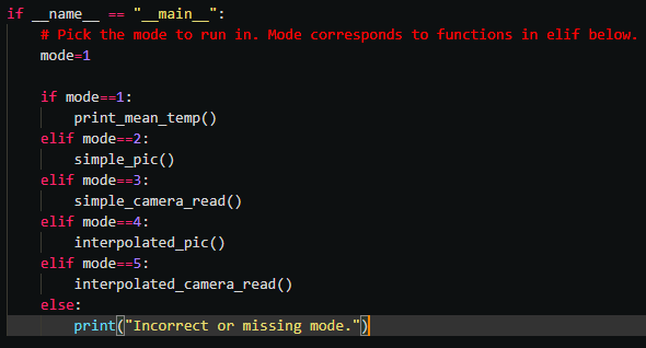 The running modes available for the Matplotlib Approach
Run this by executing the icon or going into the folder in the terminal and typing python3 followed by the filename. The mode from the number chosen will execute.
In the video modes, the video will continue unless/until an error occurs, the terminal window is closed, or the code in the terminal is halted.
OpenCV Version - Local
The OpenCV Local version can be found in the sequential_versions folder under the name opencv_therm_cam.py. It has two running modes which can be switched via the number at the bottom of the file, but the default is the video mode which is likely all you need if everything is installed correctly.
Run this by executing the icon or going into the folder in the terminal and typing python3 followed by the filename.
This version of the code was later rewritten to be class-based, and the result is pithermalcam/pi_therm_cam.py and is the camera method used by the PyPI install version of the code.
In using the camera I quickly found that it was useful to be able to change a number of features as the camera was running. Let’s discuss these here:
Colormaps
The colormap used can sometimes make a big difference in what is easily visible or not. In this clip, for example, you can see both my body heat on the side and two cold windows in the background. I cycle the colormap in this, showing how much it can make a difference in how easy/hard it is to see differences.
 Different colormaps make it easier to see important areas
Note: It’s hard to see in the compressed gif here, but the colormap in use is shown in the white text at the top.
The contrast in the image also makes a big difference. E.g. as I move out of the picture in this clip, the smaller temperature differences in the image become much more visible, making the impact of the windows much clearer. Again, different colormaps can help highlight areas of interest here too.
 As I leave the image, my bodyheat being removed makes the temperature difference between the windows and wall more visible
Interpolation Algorithms
Also, the process of blowing the image up larger requires zoom/interpolation algorithms of various sorts. E.g. here is a picture of me with the Matplotlib approach before interpolation (i.e. just the raw data as an image):
 The raw temperature data as an image.
Now change the color scheme and interpolate for a cleaner/clearer picture:
 The data interpolated. Note the clarity of the border between my body and the surroundings.
Apart from having evidence that my hands aren’t just feeling cold but actually ARE cold, this image highlights particularly how good the Matplotlib approach (which uses the SciPy library for interpolation) sets the coloring in a way that makes edges clear. The white line surrounding the red of my body makes the boundary much more visible.
OpenCV, in contrast, has a number of interpolations algorithms, but most of them don’t function as well with boundaries like this, and the default colormaps weren’t as useful. As a result I used the cmapy library to import a handful of Matplotlib colormaps (the ones chosen are visible in the cycling colormap gif above), and now we can also cycle interpolation algorithms. Here I cycle through all of them, using the same colormap as the above Matplotlib image:
 Cycling through the various interpolation algorithms. SciPy is the algorithm used by the Matplotlib approach.
The interpolation algorithm used is shown in the white text at the top of the image. Of note, cycling in this way allows us to us simplistic algorithms at the start that are showing pretty much just the raw data (useful in some cases to see what’s actually going on before interpolation). Also, the last two interpolation algorithms used are based in part on the Matplotlib approach. The first of them, Scipy, uses exactly the same Scipy-based algorithm the Matplotlib approach used. As you can see in this gif though, using it can be a bit slower or glitchy. To gain the clearer quality of the Scipy approach but the speed of OpenCV the Scipy/CV2 approach at the end uses Scipy to scale up partially, and then OpenCV to scale the rest of the way. This seems to work almost as well as Scipy alone, but without as much of a speed hit.
Other Options
Finally, a few other simple options were added.
- The temperature units shown in the text of the image (which are relative by the way, not absolute) can be toggled between Fahrenheit and Celsius.
- Simple filtering can be turned on. I tested a number of filtering algorithms but not many make much difference; the best I could find I left here, but the impact is minimal.
- Snapshot saving - When moving around the house evaluating, it’s useful to be able to take pictures from the video, so snapshots can be saved.
- Finally, exiting can be annoying if the terminal is behind the video, as you need to move the video to reach the terminal, so Esc is set to shut the script down.
All of these options can be controlled while the video is running using the following keys:
Esc - Exit and Close.
S - Save a Snapshot of the Current Frame
X - Cycle the Colormap Backwards
C - Cycle the Colormap forward
F - Toggle Filtering On/Off
T - Toggle Temperature Units between C/F
U - Go back to the previous Interpolation Algorithm
I - Change the Interpolation Algorithm Used
The thinking here is simple: S for Save, T for Temp, F for Filter, C for Colormap, I for Interpolation, and in those last to cases the key just to the left to go back.
Viewing remotely on the Pi
If, like me, you don’t have a screen for your Raspberry Pi, you’ll likely be remoting into the Pi for the two options discussed above. Both show live video on the screen and you’ll want to see that as you move around. I mentioned remoting in via SSH for VS Code development earlier, but for viewing the video I used two different approaches: the first was VNC Viewer, which comes with the Raspberry Pi and can be enabled in Raspbian. This is traditionally how I’ve connected to my Pi.
On the advice of some online forums however, I also tested the Remote Desktop program included in Microsoft Windows. As the forums had suggested, I found this connection to be a bit more stable and reliable when trying to view live video on the Pi and simultaneously moving around the wifi network. Connecting is a simple as opening remote desktop (often pre-installed on Windows and available in the Windows store and for Android and I believe Mac devices) and typing in the IP address and username of your Pi.
These two options were enough to cover my need for this approach, and I’d recommend others who are doing this consider these options.
If, however, this approach seems at times cumbersome or more error prone, the web server version might be for you:
OpenCV Version - Web Server
After testing the other two options I came to the conclusion that a better approach for using the camera via the internet would be to stream the video live to a webpage where multiple other computers or phones could all easily pull it up in a browser. Fortunately there was a similar project online in the guise of a motion-detecting camera project which I could use as a baseline for this. As such, the OpenCV code is connected in this piece to a basic Flask server which streams the video live to any computer on the network.
In the process of making this conversion, the OpenCV code was also refactored into a cleaner object-oriented class to be cleaner and better encapsulated. If others wish to develop this project further or use the camera functionality in another project I’d suggest starting with this class for a cleaner, simpler, and self-contained entry point.
Furthermore, the flask webpage that connects to this was set up to enable all the functionality of the various keyboard commands discussed in the OpenCV section via buttons on the webpage. This allows multiple browser windows or machines to all connect to the video stream at the same time and any can control the colormap, interpolation method, temperature units, save snapshots, etc.
To initiate this, either click the “Run Flask Thermal Camera” icon, if you set it up, or initiate the web server in python 3 with python3 web_server.py. When it begins it will show the local IP address to log onto:
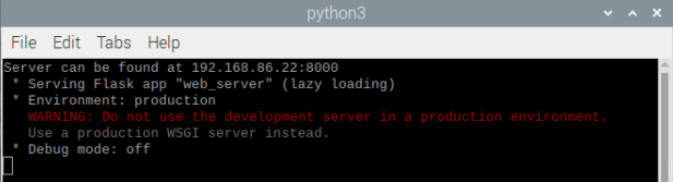 The web server code displays the address to connect to before starting the Flask server.
In this case the user simply opens a browser and goes to 192.168.86.22:8000 in order to pull up the resulting webpage with the live feed:
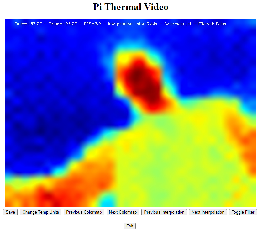 The flask-based server allows web browsers to view and control the live video feed.
The IP address for this can also be fixed by setting your router to reserve an IP address for your Pi.
Of note: This address will only be accessible from inside the same network. If you wish to set this up for external access research how to make a flask server accessible online.
Image Saving Note
Several of these features include the option to save snapshots of the video feed. The code versions in the sequential_versions folder use a sequential_config.ini file to set the location. The rest of the project defaults to the location /home/pi/pithermalcam/saved_snapshots/. If this needs to be changed it can be passed in via the “output_folder” parameter any time the camera is initialized.
Results
Having put all this together, the big outstanding question is, how does it work? Is it useful enough to identify insulation issues?
It is again worth noting that a higher resolution (i.e. much more expensive) camera would make this much easier. The lower resolution means it’s harder to figure out what a hot or cold spot is at times, and in my use I found it was both helpful and, now and then, necessary to change the color map and interpolation scheme as I was using the camera to figure out what was going on.
This is another instance in which the 110 Degree camera viewing angle is also harder to work with; if the camera is pointed at a wall, the viewing range is so wide that it’s sometimes hard to tell what is what. In a number of cases it was necessary to get very close to something to figure out what was going on. Sometimes it was also useful to hold the camera still and have someone put their hand on a physical object to determine what something was. (e.g. this red section is that angle of the wall there I think, can you put your hand on it to make sure?)
The 55 Degree camera would, again, likely be much better for this. Having the same number of sensors over a smaller viewing range would give a more nuanced view of what’s happening, and would also allow the camera to be more useful at a greater distance.
This ultimately just means that the 110 Degree camera is a bit more work though, the end result can still be quite useful. As it need be used only once for the thermal evaluation though the extra work isn’t a huge issue. And, as I said earlier, for longer term security camera usage the 110 Degree camera is likely much better as it can cover a much wider area when watching for the presence of a warm body.
Initial Results To begin with, some basic pictures were taken of the workstation. Below are real images with a corresponding thermal image to compare for a few of these. Click an image to enlarge.
Here the heat from the screen and laptop is visible fairly clearly.
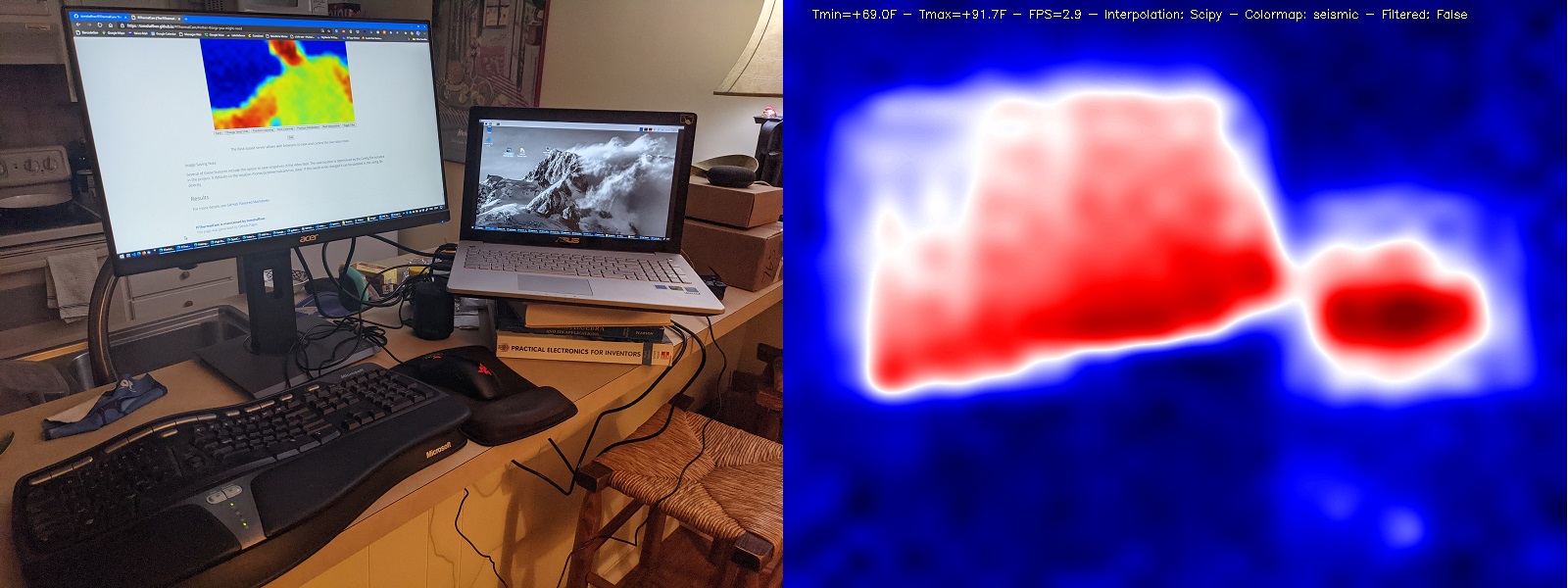 Image of a screen and laptop, normal and thermal.
Here a ceiling light and windows in the background show the heat of the former and the coolness of the latter.
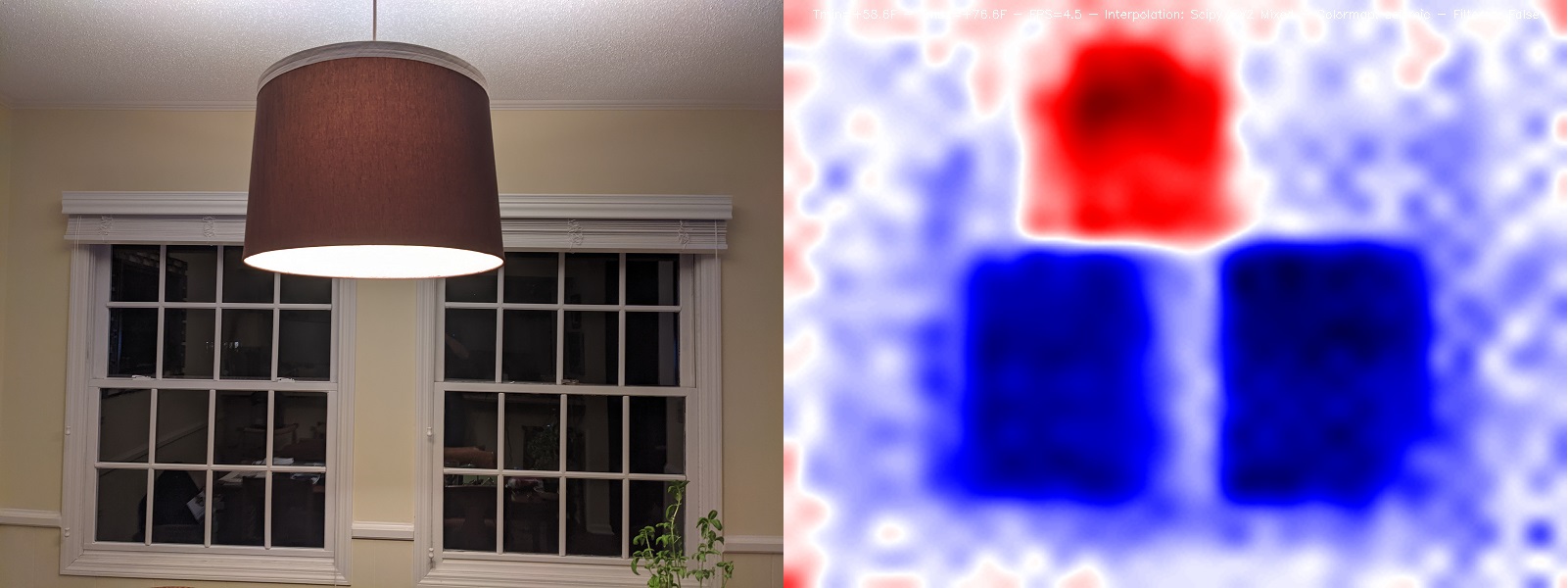 A light and windows showing heat and cold respectively.
To play around with the camera a bit, a number of pictures were taken around a running sink, where the water temperature could be varied. Here’s the sink via a normal camera:
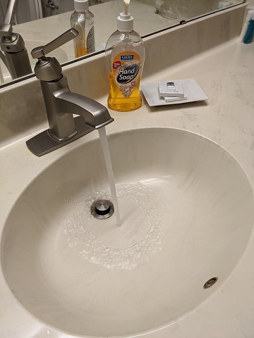 A sink with running water.
And here’s the sink with the water at cold and hot settings:
 Sink with cold and hot running water respectively.
Then I took my hand and placed it in the image under the water. In the right image I ran the cold water over the palm of my hand (it also ran down my little finger) and then took a thermal picture; the cold from the water makes the heat from the center of my hand invisible, or even colder than the background. In the left image I then covered my entire hand in cold water and held it behind a stream of hot water; the end result shows the stream visible and my arm down to a bit above the wrist. Beyond that my hand is completely invisible where the cold water had covered it:
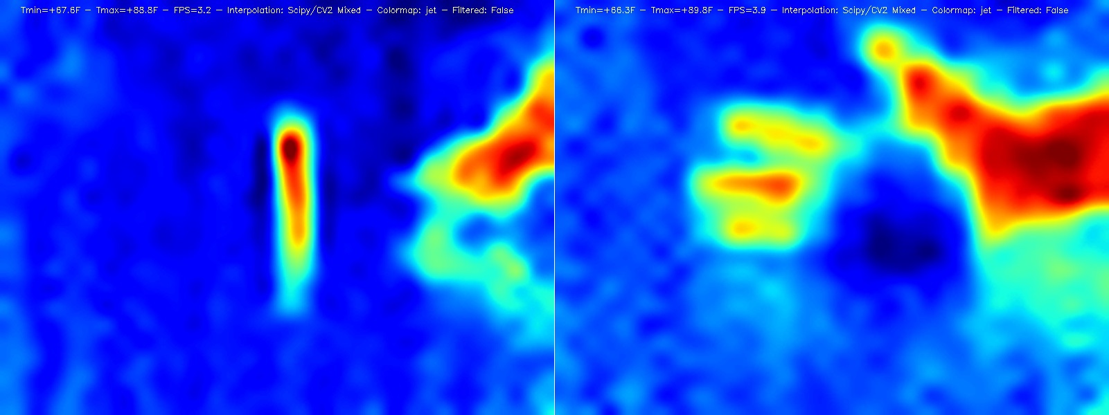 A hand covered in cold water, and a hand with cold water covering the palm only.
Seeing this was interesting, and kind of cast in a different light all those movie or TV shows where someone is facing a thermal camera in some heist.
Evaluating the House for Insulation The next question was, what heat problems are there in the house? I covered a lot more than just the below, but here are some highlights.
First, to evaluate the impact the curtains in my living room, I opened one of them; the cold of the door is clearly visible in the opened area:
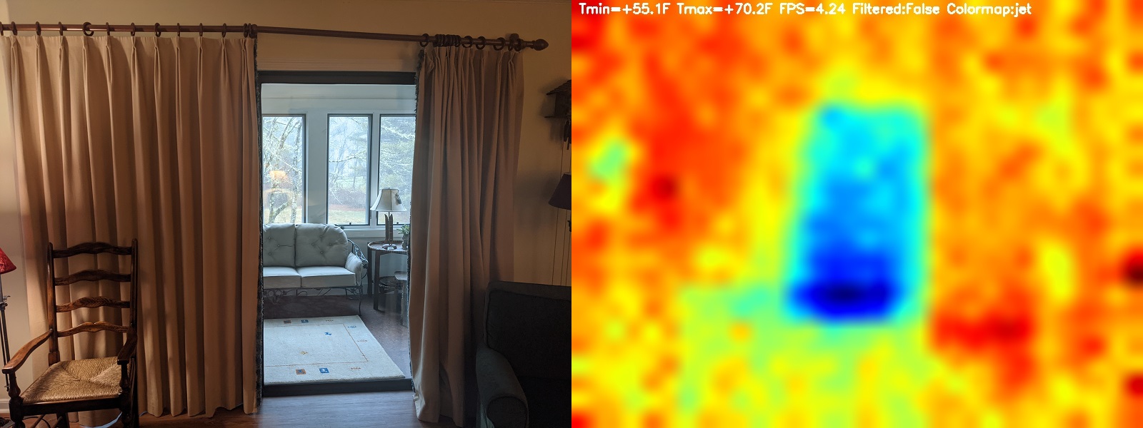 The effect of curtains visualized.
Note: The angle of these two pictures isn’t exactly the same.
Next I went into the basement and took a number of pictures. Of particular interest here, the soil stack (black pipe carrying waste water out of the ceiling and into the wall) was the hottest item in this picture! I checked after and it turned out someone had taken a hot shower not too long before.
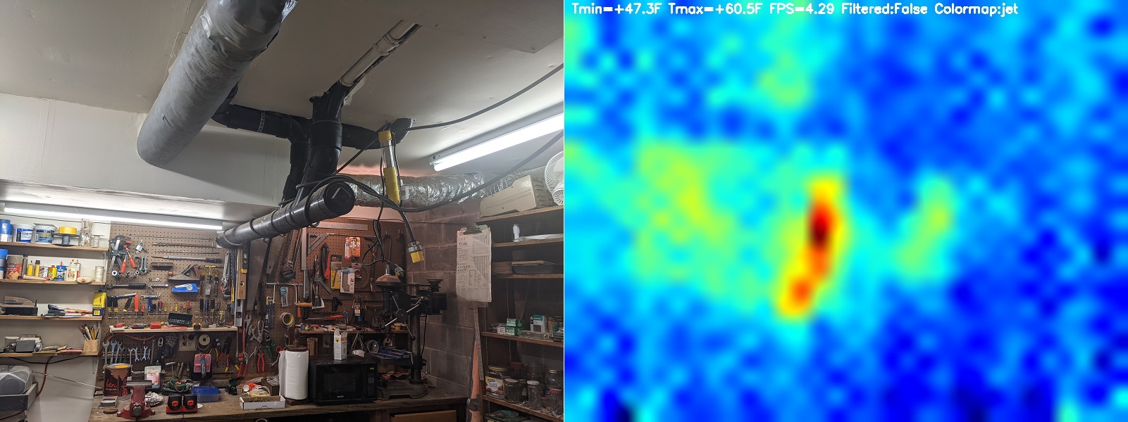 Waste pipe coming out of the ceiling.
Note: Again, the thermal picture and real picture are taken from slightly different angles here.
That waste pipe continues through the wall and into another basement room, and in that room the heat from that pipe is again the hottest thing around:
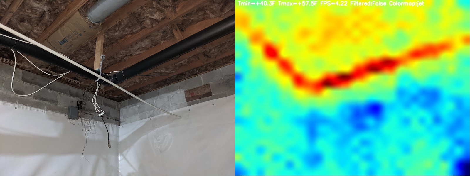 Waste pipe continuing.
I hope to do further testing of this pipe when it hasn’t been used recently to see how much heat loss there is otherwise. It’s still an open question whether this heat is just from the recent shower or if that pipe is always warm, indicating heat from the apartment above is being lost through it, in which case it might be worth insulating the pipe.
In the second room there’s also insulation in the ceiling preventing heat loss through the floor of the apartment above. Evaluating sections of that insulation highlighted one section where the insulation between two particularly close joists is actually simply missing:
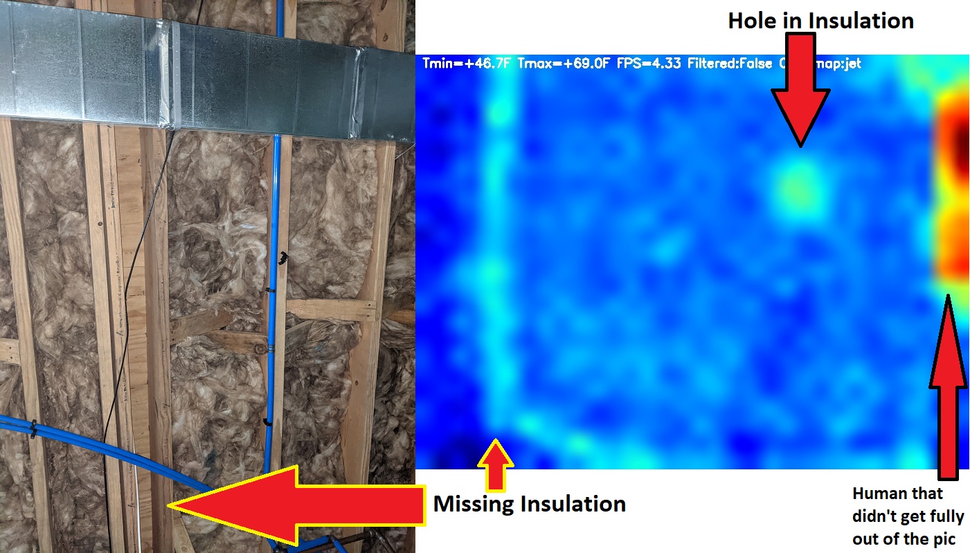 A section of insulation missing underneath a floor, and a hole in that insulation.
Of note, not only is there greater heat in between those joists, but a small area of insulation in another section is also leaking heat, indicating it’s either bunched wrong or there’s a thin place that could use some patching. The entire ceiling here could use an evaluating to find other sections of insulation that are missing or leaking heat.
In the garage, there was some debate about whether the garage door itself was the major point of heat loss or if the cinderblock walls were just as bad. In particular, the cinderblock wall has a crack just to the left of the door, and it was thought that insulating the door itself might be a waste if the wall leaked just as much:
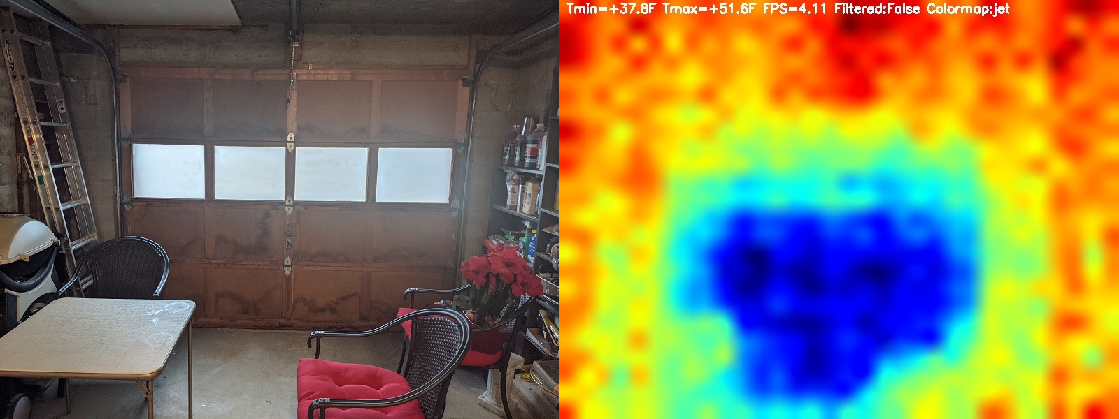 Heat loss via the garage door.
Here we can see that’s not the case; the wall might be losing heat, but the door is losing it MUCH faster. If that crack makes a difference it’s too small even to see here.
Note: The temperature differential shown is only about 14 Degrees F. The temperatures in the text are relative so the absolute value is almost certainly wrong, but the difference between them should be ballpark correct and represents the differential between the hottest and coldest parts of the picture. Note that the walls immediately around the garage door ARE cooler than the hottest part of the picture (dark red in the ceiling), but those walls are still warmer than the door itself. As such, the theory about the wall losing heat is likely correct, but the greater heat loss through the door would indicate that either a new door or insulation for it would, indeed, help keep the space warmer.
While looking at that garage picture I was a bit surprised at how hot the ceiling was. Particularly interesting, if the camera turned up a bit, a beam of heat could be seen running down the ceiling (left pic below). At first I thought maybe this was the chain and motor for the garage, but if I took a picture when the garage door hadn’t been opened for a day the beam of heat was still there. Furthermore, if I turned the camera up to cover the entire ceiling, the beam of heat ran all along it, even the sections with no chain or motor. Turned high enough to exclude the door itself, the beam of heat in the middle of the ceiling, surrounded by cooler areas on either side, became obvious (right picture below):
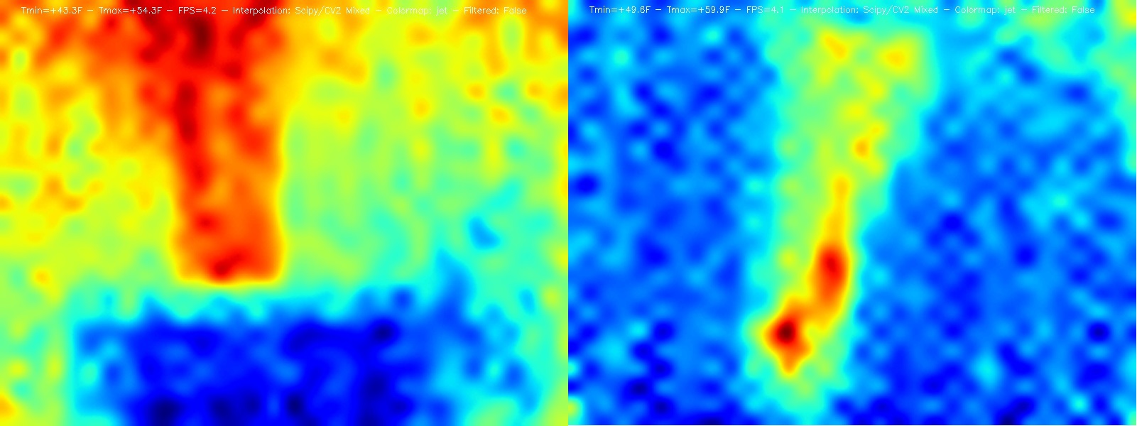 The ceiling above the garage door, showing poorly insulated
This was one of the most useful insights from the entire project. The camera is seeing heat leaking through the center of the garage ceiling, while the ceiling looks completely blank and unchanged to the naked eye. Something is going on above the surface of the ceiling that is not visible.
In trying to figure out what might be causing this, first, an access panel nearby gives a bit of visibility in the direction of this ceiling and it seems there are two boards that cover the outside sections of the ceiling, but leave the middle section open. Second, it’s believed, after asking around among those who were present during the last remodeling, that the heating duct for the apartment above runs directly through this section. Furthermore, at the time of installation this heating duct was installed without being insulated.
As such, it seems likely that some portion of the heat from this particular heating duct is, instead of being vented into the apartment above through the grate, leaking into the garage below. From there is goes right out the poorly insulated garage door, making for an overall heat loss for the entire area.
There’s still a debate about whether the best solution for this is to insulate the duct itself or to insulate the garage door, continuing to lose heat from above into the garage but potentially making the garage a more comfortable space to work in during the winter months.
In either case though, the camera has already been deeply useful in figuring out what’s going on and what to do about it.
There were other examples of the camera helping find holes or issues in the current insulation. What’s shown here is already enough, however, to demonstrate the usefulness and efficacy of the MLX90640 for this purpose.
Finally, here’s a brief larger video of the camera cycling interpolation algorithms and colors as a demonstration. The gif reduces the quality a bit, so what you’ll get is even better and faster than what you see here:
 Live camera cycling through interpolation and color modes and varying view.
Further use thoughts What’s not shown here are pictures taken from the outside of the house of heat coming out. Some basic testing was done for this, but on the days in question this testing was limited due in part to concerns about water on the device (it was raining), and because the efficacy of those images was limited. The device itself worked fine from outside, and in a few cases identified much more clearly which windows are currently leaking much more heat than others, and which windows already seem to be high enough quality to not be an issue.
From outside however, the distances from the objects being considered become greater, and as a result the problems of having a lower resolution higher viewing angle camera become more apparent. This is one area where the 55 Degree viewing angle camera would likely be much better.
Also, the wifi in this particular house extends only so far from the building itself. As such, the method used here of streaming the video over wifi became more and more unstable the further from the building the camera was. With a better network connection or a screen attached to the Pi and the video being displayed locally on the screen (rather than via the web server approach) this method would be much easier. Pictures of this type will likely be quite useful as well in identifying other areas of heat loss for the house.
For purposes of this demo however, the above were considered sufficient to showcase the efficacy of the camera for this purpose.
Conclusion
While the MLX90640 will never provide pictures or video of the level of fidelity that some much more expensive professional cameras provide, what’s shown here is more than enough to demonstrate the efficacy and usefulness of the camera both for entertainment purposes, as a security camera, and for a thermal evaluation of a house. The version of the camera with a narrower viewing angle (55 Degrees instead of 110) would likely be better for the thermal evaluation purpose but be of less value as a security camera.
Regardless though, it’s clear that the market has now reached the point where affordable thermal cameras can be effectively used to evaluate the insulation quality of a house. This article, and the accompanying open source library on Github, are provided for others to get started quickly and easily in doing their own work, or to use as a springboard for further development of their own.
Further Development
There are a few next steps for development that have not (to date) been undertaken. Pull requests that complete these would be welcome:
- Look into camera speed more. The article on which the Matplotlib approach was based had a useful discussion of framerate and camera speed. In the author’s case, a much higher baudrate and some tweaking of the size of the final image could result in much better framerates than I ever achieved. Easier options to tweak all these factors in the library are worth setting up.
- Set up a security camera mode: The web server version of the library can currently be used as a basic security camera version, but another mode could be added to do this more effectively. In particular, the article used to set up the web server version could be mirrored to check and see where movement is occurring in the frame and where the background is remaining unchanged. This could also then be set up to raise a warning of some sort when movement is detected.
- Convert security camera mode to enable viewing it outside the local wifi network.
Of note on the second point, the normal use of the camera indicates some measure of noise that’s greater than a typical (non-thermal) camera experiences, so the approach used in the original article on this topic would likely need to be enhanced to allow for greater noise levels without triggering. Similarly, the fact that temperatures are shown in a relative way might impact how movement works. And finally, temperature fluctuations of the general environment throughout the day would need to be accounted for to avoid beams of sun or the simple onset of a wind or night being viewed as motion.
Issue Reporting
Where issues, problems, or concerns come up, they can be reported in the Github repository that corresponds to this page. Bugs or problems can be entered as Issues, and general questions or discussion topics can be created in the Discussions section. A fast response from the author is not guaranteed, but I will do my best to support/respond as time allows.